
Guard and hazard height
Review the height of the protective structure, the height of the hazard and their horizontal separation together.
Machine guarding design guide · UK
A practical guide to positioning perimeter guarding around machinery—considering reach, mesh aperture, floor gaps, access points and the actual hazard.
The short answer
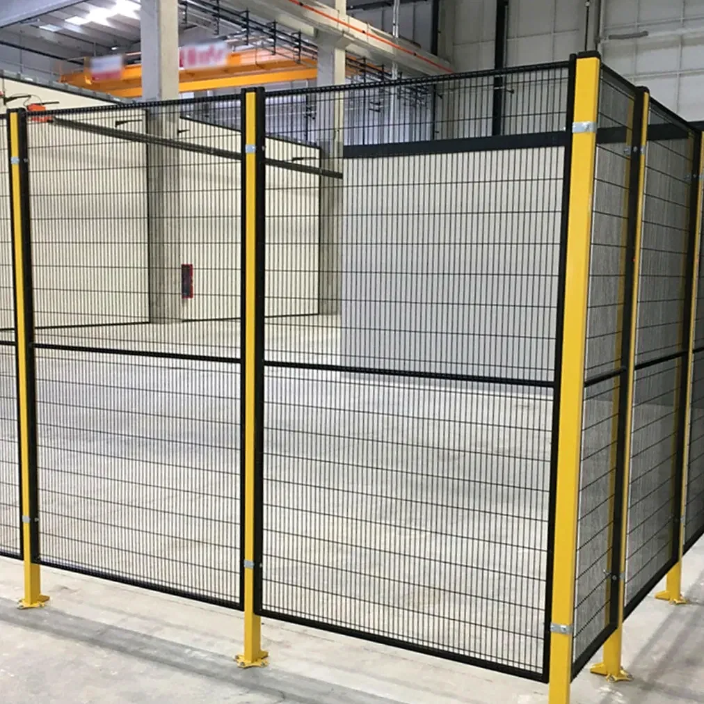
The fence height and its distance from the hazard work together. Both must be selected from the machine risk assessment and the ways a person could reach the danger zone.
A suitable layout considers reach over, through, under and around the guard; the mesh aperture; hazard and guard heights; nearby footholds or platforms; floor clearance; gates; product openings; and the machine's stopping behaviour. A dimension copied from another installation can be unsuitable when any of those conditions change.
Six connected checks
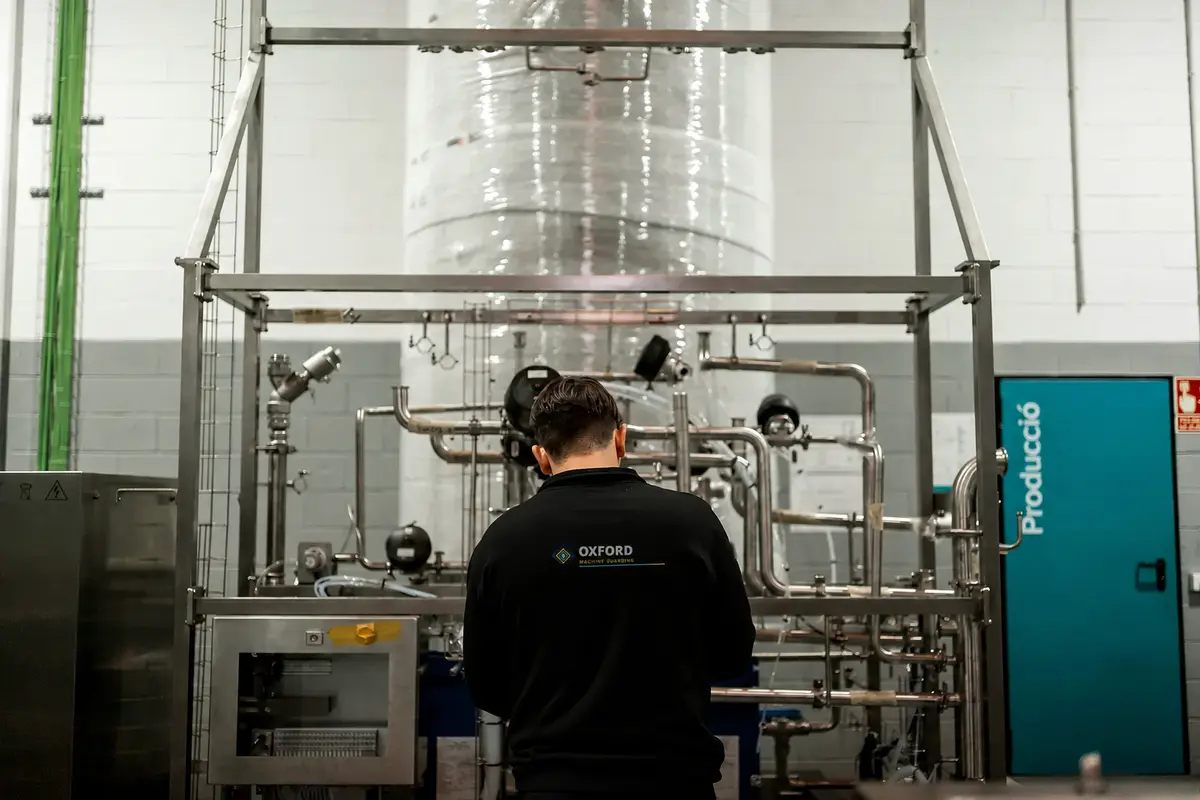
The finished boundary must prevent access in every credible direction, including at interfaces that are easy to overlook.
Review the height of the protective structure, the height of the hazard and their horizontal separation together.
Match the clear opening to the body part that could enter and keep the hazard beyond the applicable reach distance.
Check uneven floors, changes in level and openings beneath panels for hand, arm, foot or leg access.
Close routes beside walls, columns, conveyors, services and machinery where someone could bypass the main panel run.
Consider horizontal rails, frames, pallets, platforms and building features that change the effective approach height.
Control personnel access and material flow using a safety strategy suited to the hazard and production task.
Layout review sequence
A defensible fence line can be explained as a chain of project decisions.
The sequence below helps expose gaps early, before posts are drilled or an access gate is placed where it disrupts safe operation.
| 1 · Identify | Locate hazardous movement, energy, temperature, ejection and trapping points. |
|---|---|
| 2 · Observe | Record operation, cleaning, adjustment, fault recovery, maintenance and material flow. |
| 3 · Map access | Check reach through, over, under and around, plus whole-body entry routes. |
| 4 · Select geometry | Coordinate aperture, height, stand-off, floor gap, returns and close-outs. |
| 5 · Control openings | Define gates, interlocks, guard locking, transfer apertures, reset and restart. |
| 6 · Verify | Inspect the installed boundary and test agreed safety functions before handover. |
Standards and UK duties
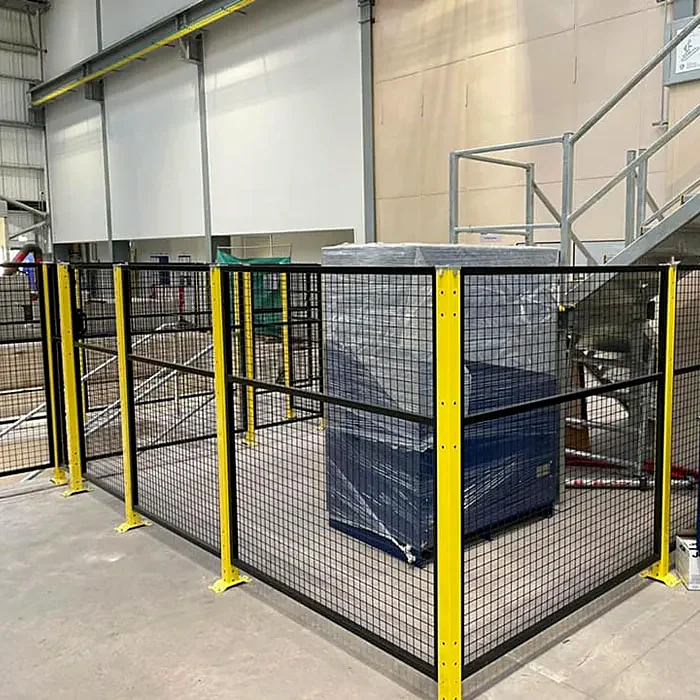
ISO 13857 provides safety-distance principles for preventing upper and lower limbs reaching hazard zones. ISO 14120 covers general requirements for fixed and movable guards.
Interlocking devices are addressed by ISO 14119. In Great Britain, the HSE's PUWER guidance explains employers' duties for work equipment. Applicable legislation, designated standards, machine-specific standards and the current editions should be checked for each project.
This page is planning guidance, not a substitute for a risk assessment or validation of a particular installation.
Frequently asked questions
There is no universal safe fence height. The required height depends on the hazard height, the horizontal distance to it, possible reach over or through the guard, footholds, nearby structures and the risk assessment. The layout should be checked against the current applicable standards before dimensions are fixed.
The separation distance depends on the opening size and shape, the body part that could reach through it, the hazard position and the relevant safety-distance data. Larger apertures generally require greater separation. Stopping performance and the possibility of reaching under, over or around the guard also need review.
No. Mesh aperture is only one part of the design. The guard height, distance from the hazard, floor gap, panel strength, routes around the ends and access through gates or process openings all affect whether the boundary prevents access.
BS EN ISO 13857 addresses distances intended to prevent upper and lower limbs reaching hazard zones, while BS EN ISO 14120 covers general requirements for fixed and movable guards. Interlocking devices are addressed by BS EN ISO 14119. The project risk assessment and current editions should determine which requirements apply.
Provide the machine layout, hazard locations and heights, intended panel and aperture, floor level, nearby platforms or footholds, gate and material-opening positions, access tasks, stopping information and photographs. A survey is useful when those details cannot be confirmed from drawings.
Have a proposed fence line?
Send photographs, a drawing and the access tasks. We will identify the information needed to progress the design or quotation.